A Handheld Battery-Powered Line Scan Camera

Introduction
Most digital cameras are area scan cameras. They use a sensor with a two-dimensional grid of light-sensitive points to capture an image. Area scan cameras excel at capturing stationary subjects; however, they can only capture moving subjects if the exposure time is fast enough to avoid motion blur.
There is another type of camera that is only common in industrial machine vision called a line scan camera. It uses a one-dimensional line of light-sensitive points that captures only one “line” of an image. To capture a full image, the subject must move relative to the camera so that it can be “scanned”.
For certain industrial applications, line scan cameras have several advantages over area scan cameras. They can capture at very high line rates, often tens of thousands of lines per second, allowing continuous imaging of fast-moving subjects. Because only a single line needs to be illuminated, the lighting can be made very consistent and uniform across the entire image. This is much easier to achieve than uniformly lighting a large two-dimensional area. Line scan cameras are well suited for inspecting objects moving on a conveyor belt, such as packages or food products. They are also common for imaging continuous webs of material like rolls of paper, sheet metal, or textiles.
Because capturing a clear image requires the subject to move at a constant speed relative to the camera, line scan cameras are rarely used outside of these industrial settings. One notable exception are photo finish cameras used in track-and-field and horse racing. These cameras are line scan cameras oriented perpendicular to the finish line. As subjects cross the line, the camera builds up an image that precisely captures the order of finish.
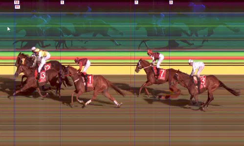
A capture from a photo finish camera (source)
Line scan cameras have also been used for artistic photography, most notably by photographer Adam Magyar. Magyar home-built a line-scan camera using the sensor from a document scanner1 and used it to create panoramas of subway platforms and city streets. Daniel Lawrence Lu has also blogged about using an industrial line scan camera to capture images of trains; his blog posts inspired me to take up this project.
In order to capture an accurate image, it’s important that the line capture rate is synchronized with the speed of the object. If the camera is capturing too slowly, the image will look squished. If the camera is capturing too fast, the image will look stretched.
Industrial line scan cameras typically connect to an encoder to synchronize the line capture rate to the exact speed of the moving subject. When this isn’t possible, the camera can run in “free run” mode where it captures lines at a fixed frequency.
Packaging a Line Scan Camera as a Handheld Device
Inspired by Magyar’s photography and Daniel Lu’s posts about taking a line scan camera on the go, I decided I wanted my own portable line scan camera. Just like a modern digital camera, I wanted it to be
- battery powered
- small enough to be carried by hand
- capable of capturing and storing images internally
- equipped with a screen for reviewing captured images
Hardware design
Since I already had a Vision Datum MARS4096C-L28GC industrial line scan camera available to me, the choice of camera sensor was already made. The rest of the device was built around it. This camera unit features:
- a 4096x2 pixel2 sensor with a Bayer RGGB color filter array
- Ethernet connectivity with GenICam compatibility over the GigE Vision protocol
- 12v – 24v power input
The camera unit has a sensor, onboard processing, and some buffer memory, but it’s not a general-purpose computer. It must connect to a host computer that processes and stores the image data. In an industrial application, it would connect to a machine vision computer. To act as the host device, I chose the Seeed Studio reTerminal, which is a Raspberry Pi CM4 packaged with a 5" touch screen. I got the version with 4 GB of RAM; however, in hindsight, I should have used the 8 GB version.
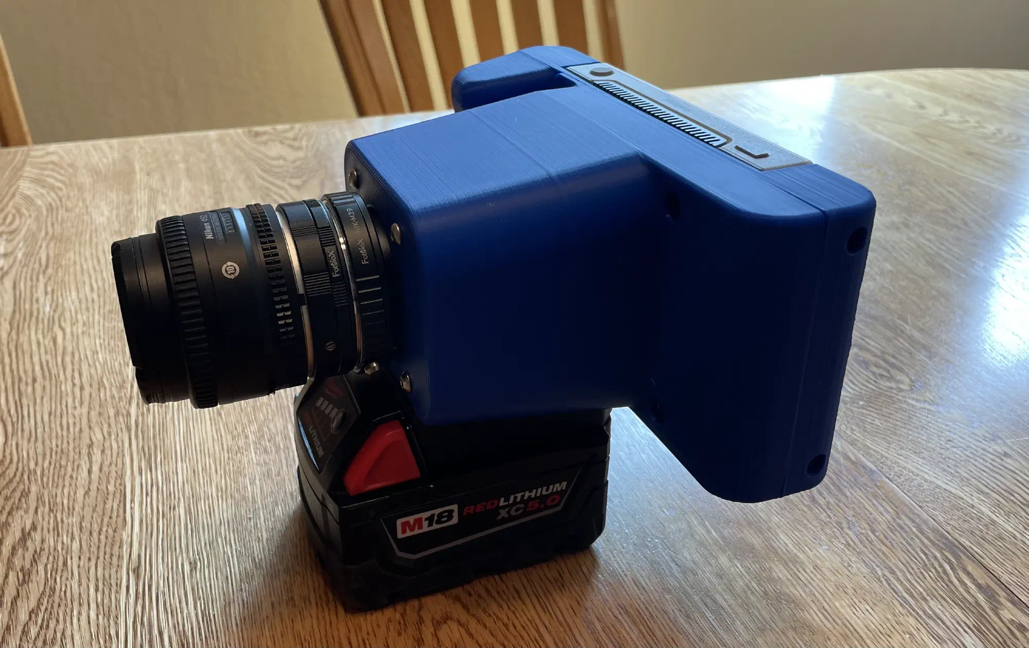
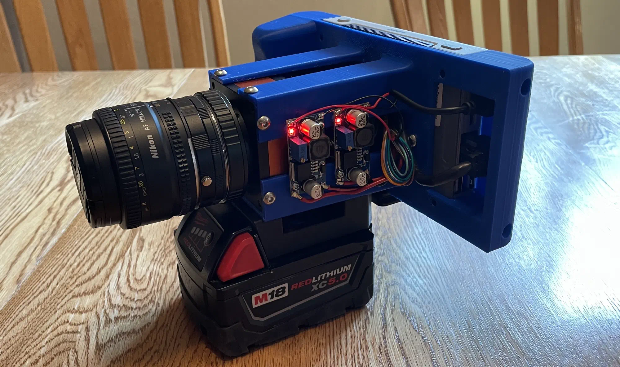
To power the unit, I found a holder for a Milwaukee M18 power tool battery. The injection-molded version is great quality, and I would use these again for other projects in the future. An XC5.0 size battery (nominally 5 amp-hours) has enough juice to run the camera for well over an hour. Two cheap AliExpress LM2596 switching voltage converters provide 12v for the camera and 5v for the Raspberry Pi. These converters work fine but make an annoying audible whine under load.
For interconnection:
- For connecting the camera to the Raspberry Pi, I found a right-angle Ethernet patch cable. I had to cut the cable to length and re-terminate it.
- For the power connection to the camera, I trimmed the cable provided by the camera’s vendor. The camera’s IO/power port is a Hirose push-pull connector, which proved to be very bulky. I tried to use a field-wireable connector, but it was too long to reasonably package within the enclosure.
Lens
One of the hardest aspects of the hardware was fitting a photography lens onto the industrial camera body. The body has an M42 threaded mount with a 12mm flange focal depth, so I needed to adapt this to accept modern photography lenses. The M42 mount is reasonably common on vintage cameras and lenses (especially Pentax); however, most off-the-shelf adapters are for putting M42 lenses on modern bodies, not the other way around.
My primary camera is a Sony A6600, so using Sony E-mount lenses would have been ideal since I already have a collection of lens options. However, E-mount lenses need to receive power and control signals from the camera for drive-by-wire focus and aperture control. I looked for an adapter to provide external power and control to an E-mount lens, but I found nothing, so this path was a non-starter.
The next best option was adapting to Nikon F lenses, since I have a few manual lenses lying around in 50mm and 35mm focal lengths. There’s no off-the-shelf F-to-M42 adapter, but I found an M39-to-M42 adapter and paired that with an F-to-M39 adapter.
Additionally, adapting the lens mount is not enough; the flange focal depth must also be considered. A lens will produce an image at a specific distance, and this distance must align with the sensor of the camera. Otherwise, the image will appear out of focus. If the lens produces an image behind the sensor, an extension tube can be added to move the sensor to the point where the image will be sharp. If the lens produces an image in front of the sensor, there is no practical way to use that lens with that camera. Fortunately, the 12mm flange depth of the industrial camera is very short, so it is possible to add a tube to be compatible with the 46.5mm flange depth required by F-mount lenses.
After much searching and a few phone calls, I found a combination of lens adapters and extension tubes that made the F-mount lenses work. The final stack-up is:
- Lens
- Extension Tube
- Nikon F-mount to M39
- M39 to M42
- Camera Body
Software
For operating the camera, I wanted a lightweight touchscreen GUI to reserve as much of the Raspberry Pi’s compute resources for capturing the image. Qt 5 with QtQuick components was chosen because I was already familiar with Qt. Qt 5 was used because it’s available on Raspbian 11 (Bullseye). I would have preferred to create a custom Linux build with Buildroot, but the Seeed reTerminal has a lot of peripheral drivers that are pre-installed in Seeed’s modified Raspbian distribution. If I had rolled my own, I would have had to get those working on my own. If I had to do this again, I’d try Rust and Slint, instead of C++ and Qt.
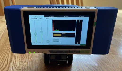
The setup interface with visualizations to help set the exposure time, gain (ISO), white balance, and focus.
The camera uses the GigE Vision protocol, which is a UDP-based protocol for transferring image and control data. On top of GigE Vision, the camera follows the GenICam API standard3. There are open-source libraries that implement these protocols, but it was easier to get started with the vendor’s proprietary C SDK, which they provide for Linux on arm64.
Since there’s no way to connect the camera to an encoder, the camera runs in “free run” mode. The ideal capture rate depends on the linear speed of the subject, the distance from the subject, and the focal length of the lens. Any image distortion caused by a mismatch between the speed and capture rate must be corrected in postprocessing. In practice, it’s best to “over-capture” by setting the frequency higher than ideal and then “squishing” the image.
To facilitate continuous capture, the camera is set with a frame size of 64 lines. Each time a frame is ready, the SDK runs a callback function and the frame is copied into a ring buffer. A separate thread reads out of the ring buffer and appends the data to a file on disk. It’s important that minimal processing be done during a capture to minimize the delay when processing each frame. If the frames can’t be processed quickly, they could be dropped.
Postprocessing
After the image is captured, it is stored as “raw” image data, which isn’t directly viewable. This raw data must be “developed” into a viewable image.
Digital cameras capture color images by putting a “color filter array” in front of the sensor. The most common color filter array is the Bayer pattern, which is a 2x2 grid with one red, one blue, and two green pixels. There are more green pixels because the human eye is more sensitive to green light.
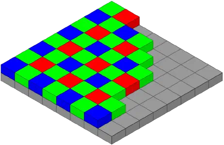
The Bayer pattern over an image sensor.
The color filter array limits each pixel on the sensor to detecting only one color: red, blue, or green. This means each pixel of the raw captured image contains only one color channel. However, on an LCD screen, each pixel has all three colors. To develop the image, the two missing channels for each pixel must be interpolated from the neighboring pixels.
The vendor SDK provides a function to demosaic the image data; however, it offers limited options which results in poor control of the final output. To allow more ergonomic editing and color correction, I implemented a converter to save the camera raw files as Adobe DNG files4 that can be opened by Adobe Lightroom, Affinity Photo, and other photo editing software. The DNG file format is public and well documented; however, Lightroom is very finicky about what it will accept. There are many “optional” fields in the file format that Lightroom seems to require, and it does not give clear error messages about what it doesn’t like about a given file.
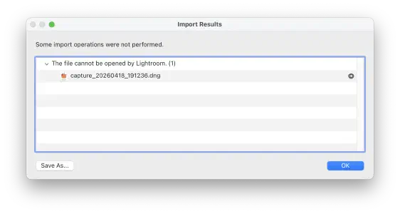
A supremely unhelpful error from Lightroom after trying to import a valid DNG file.
It took some trial and error to figure out what Lightroom wants, but I was able to get most files to open. There are still some captures that refuse to open properly, though.
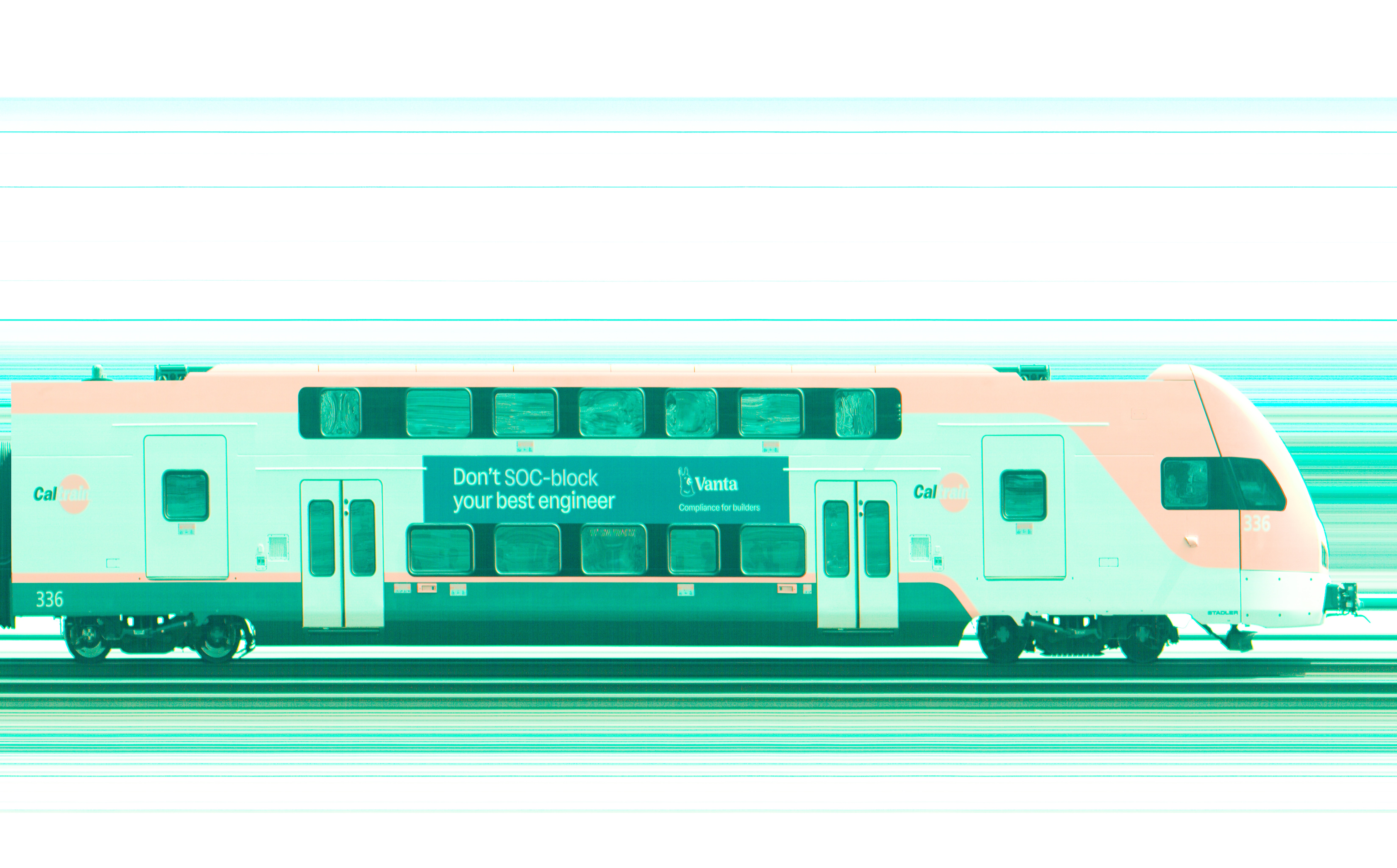
Getting the file to open is only part of the battle, however. If the raw sensor values are developed by Lightroom without any correction, the color hue is somehow simultaneously “too green” and “too red”. Fortunately, the camera has internal color correction parameters that can be read as GenICam feature nodes and written into the DNG file. These parameters help raw developing software do initial color correction. The camera also has an “auto white balance” mode that produces red, green, and blue scalar values which can be written into the DNG. However, even with this correction, the colors don’t always look right. It’s taken some manual correction to get the color close to what I perceive as “natural”.
Conclusion
Overall, I’m happy with the usability of the device. There’s room for improvement, but it is at a state where I can use it as a tool, rather than a tinkering project. I’m looking forward to finding more subjects to capture in the line scan format.
Using the drill battery as a power source has worked well; they’re robust, easy to swap out, and available off-the-shelf. The Seeed reTerminal has been a great platform for building the application on, with a touch screen that’s easy to read in sunlight and physical buttons for important functions. While there are hardware improvements that could be made, I don’t think they would make a meaningful difference in the usage of the device and I plan to focus on the software.
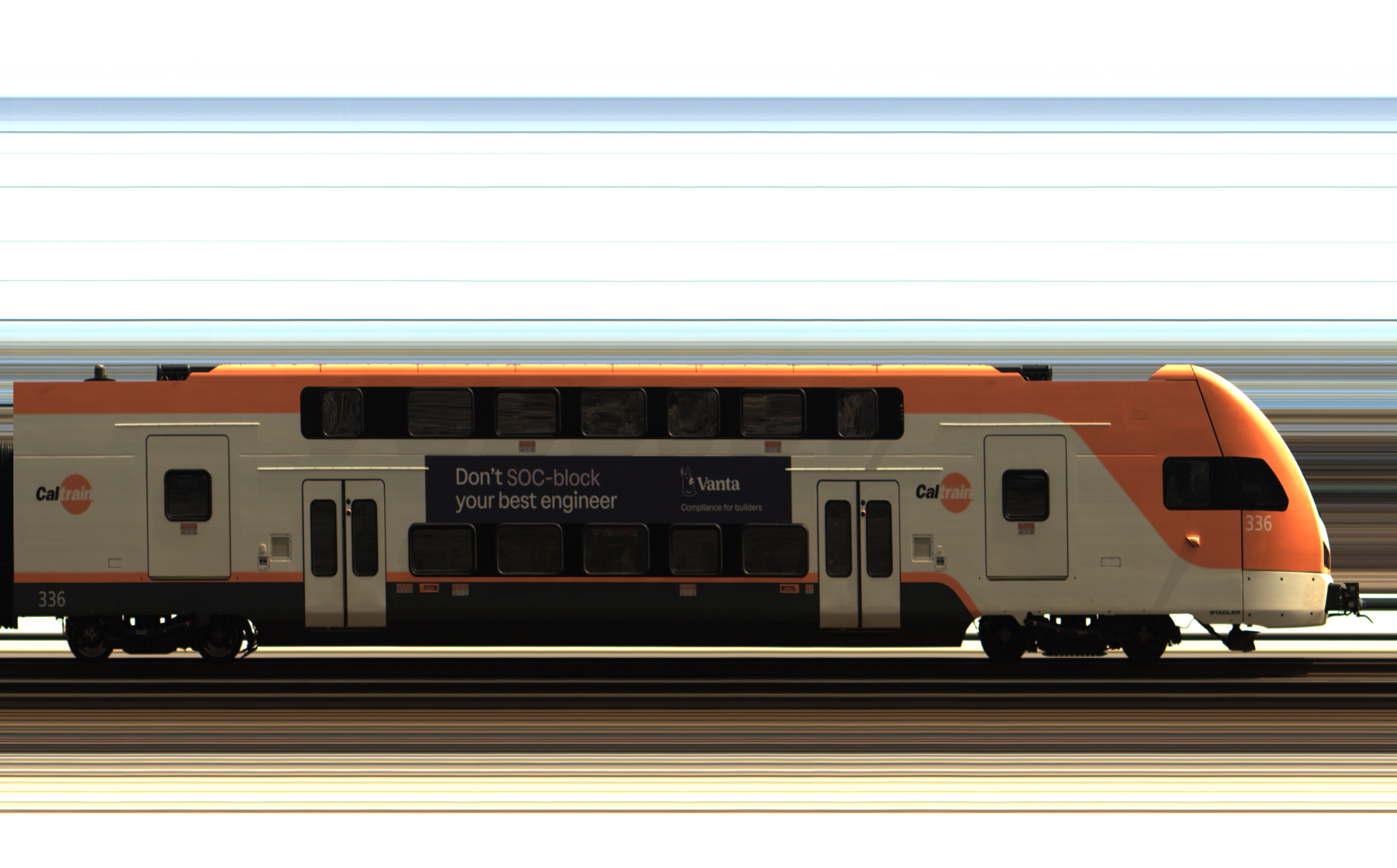
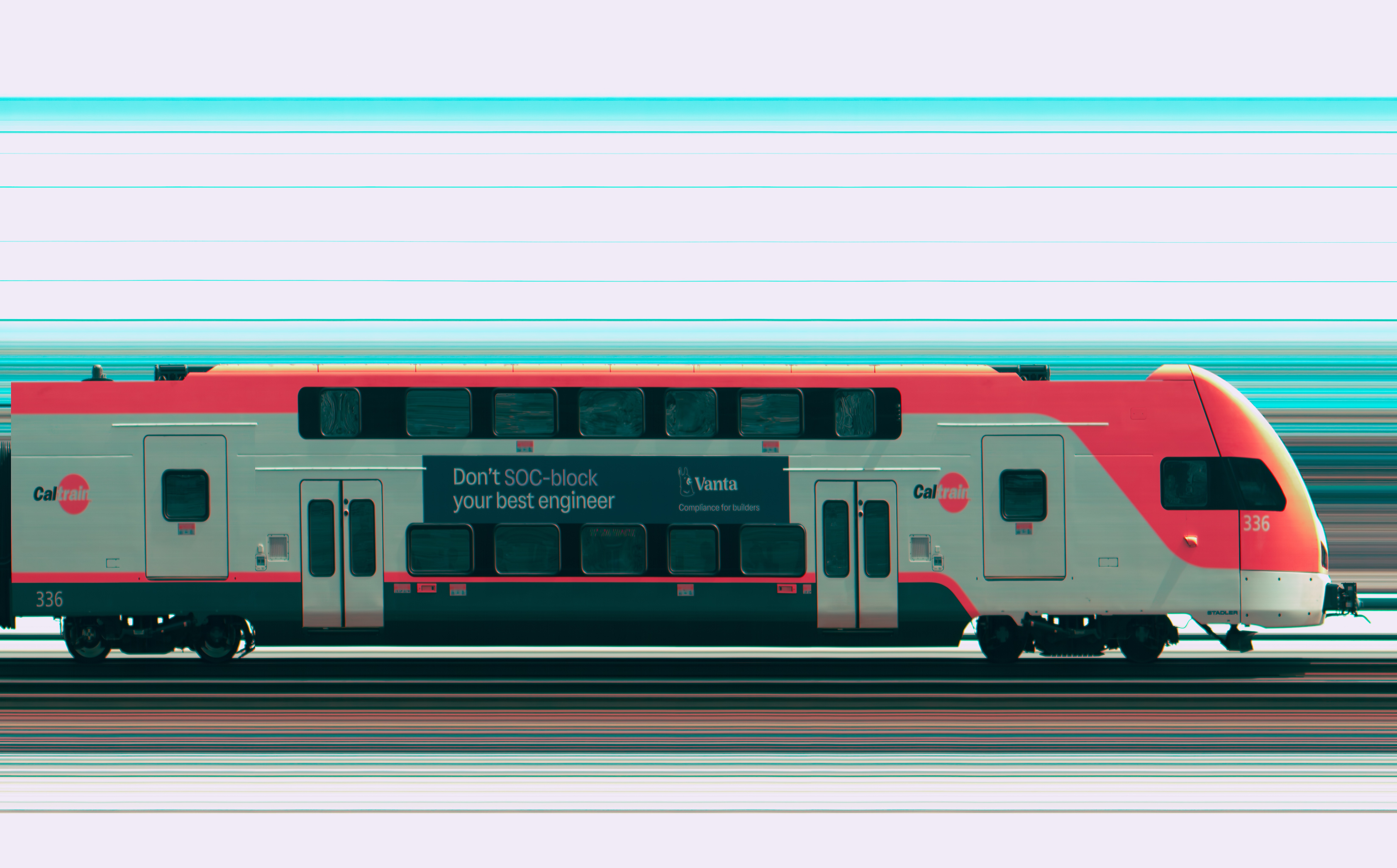
The color accuracy still needs work. It’s difficult to recreate the color science that we take for granted in our phones and digital cameras. I think a practical goal is to use Lightroom presets to get photos close, and then manually apply color corrections based on reference photos from another camera. There is also a software issue where the camera occasionally drops a frame, resulting in a 64-pixel-wide stripe missing from the image. A close inspection of the Caltrain photo will reveal a few of these defects. I think some adjustments of the Linux kernel networking settings can help with this.
Line scan images possess a unique “look” as they bridge the worlds of industrial machine vision and artistic photography. The strong subject isolation and flat lighting create a sterility that’s not seen in everyday photographs. Because the camera only captures what is moving and stationary objects are invisible, it offers a different perspective of the world. As Adam Magyar put it: the camera doesn’t capture space; it captures changes in time. I want to find out what else in the world can be seen through this lens.
Document scanners and copiers use a similar principle. A flatbed scanner has a single line of sensors that moves across the page, building up the image one row at a time. ↩︎
Why is the sensor 2px wide, instead of 1px wide? Because Bayer filter arrays are a 2x2 repeating pattern, color line scan cameras typically have two rows. Monochrome line scan cameras are actually 1px. ↩︎
GenICam is transport-agnostic and supports other transports common in industrial vision applications, such as USB3, CameraLink, CoaXPress, etc. ↩︎
Adobe developed and promotes the Digital Negative (DNG) file format as an open source raw image format with publicly available spec. It was intended to replace the proprietary file formats used by major camera manufacturers, however it received limited adoption. Major camera manufacturers like Sony, Canon, and Fuji still use their own proprietary formats and they work with Adobe to add support to Lightroom. Outside of being a major camera manufacturer, the easiest way to get raw images to open in Lightroom is to use DNG. ↩︎